Following Cart
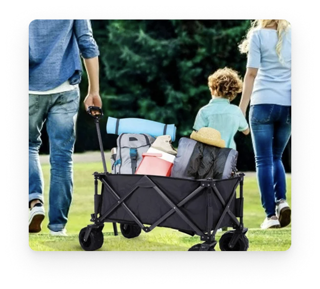
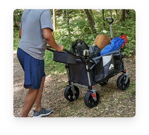
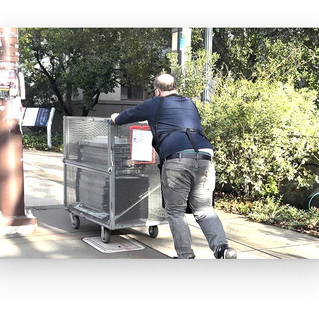
Carrying heavy gear across campsites, warehouses, or shopping areas is physically demanding — and existing electric carts still require manual steering with no obstacle avoidance or person-following capability.
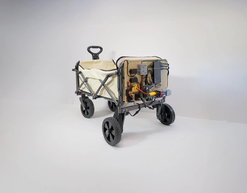
Designed and built a vision + UWB sensor fusion mobile robot that autonomously follows a user while avoiding obstacles in real-time, integrating OAK-D perception, ROS2-based control, and differential drive motor control into a complete working prototype.
Working prototype achieved real-time person tracking, autonomous following at walking speed, and depth-based obstacle avoidance — full hardware + software integration from perception through planning to motor control.
Overview
Most autonomous cart projects stop at simulation. We built the real thing — a differential-drive cart that sees you with a depth camera, knows where you are with UWB, and follows you while dodging obstacles. The system covers the full robotics stack: perception (YOLO + depth), localization (vision + UWB fusion), planning (following algorithm + obstacle avoidance), and control (ESC-driven differential drive). The hardest part wasn't any single component; it was making vision, localization, and motor control work together reliably in the real world.
System Architecture

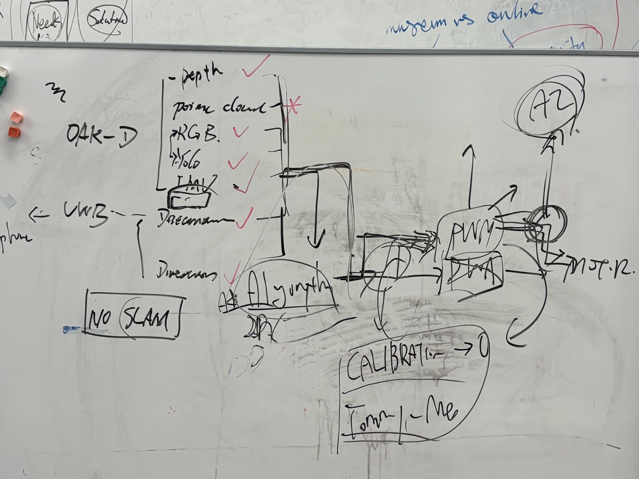
The system follows a layered robotics pipeline: Sensors (OAK-D Camera + UWB Module) feed into a Perception System (YOLO person detection, target tracking, depth processing, obstacle detection), which passes through a Sensor Fusion layer combining vision position with UWB distance/angle data. The fused target estimation feeds into a Motion Planner (follow algorithm, obstacle avoidance, speed control), which outputs ROS2 cmd_vel commands. These are converted to differential wheel speeds, sent to ESC controllers, and drive the physical cart movement.
Key Highlights
Hardware + Software Integration
most student projects stop at simulation; this project delivered a complete working prototype with AI + robotics + hardware
Multi-Sensor Fusion
vision + UWB asymmetric fusion architecture provides robust tracking even during occlusion
Full Robotics Stack
covers perception, planning, control, and hardware integration end-to-end
Process
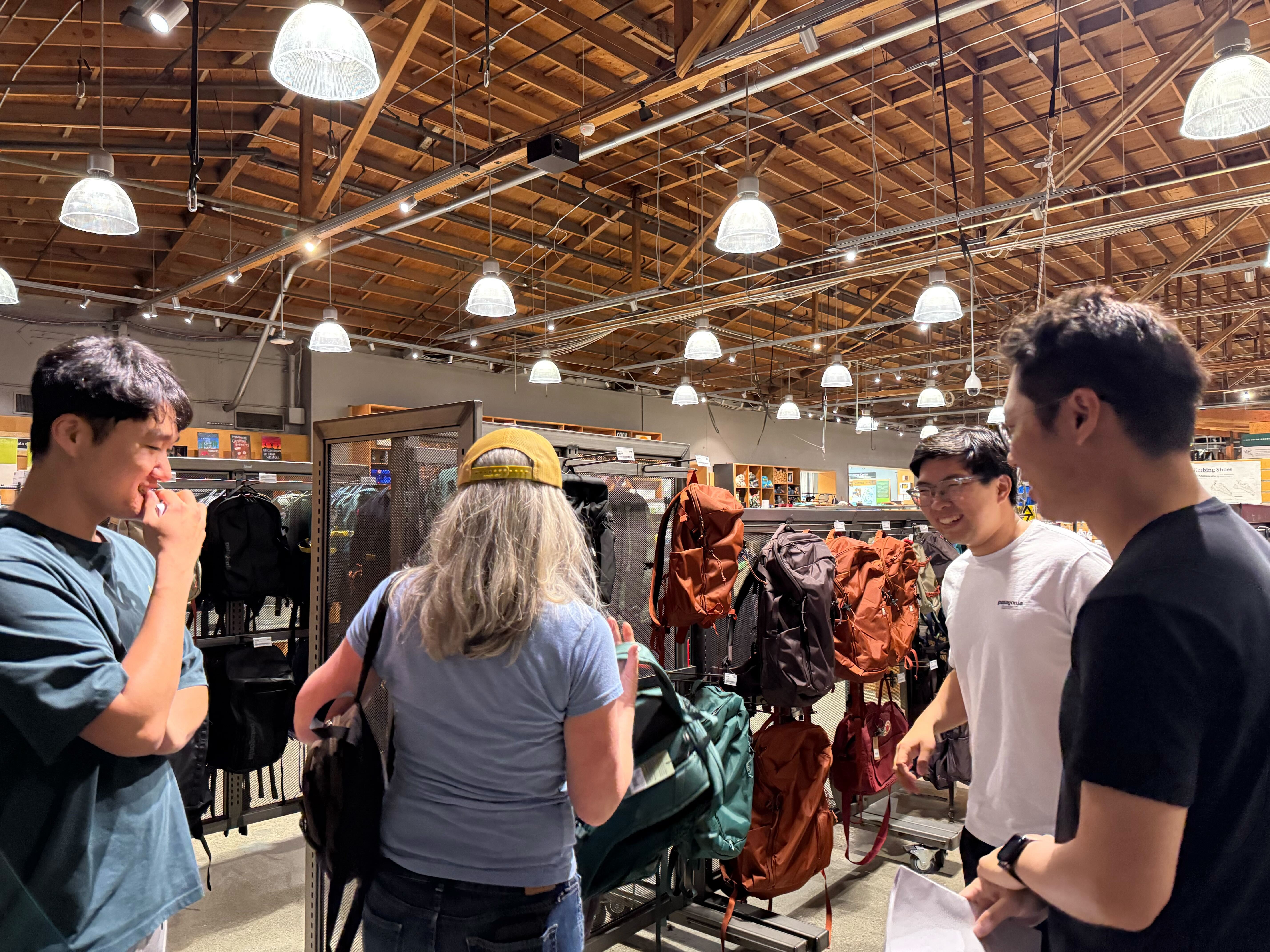
Problem Scoping & Competitor Analysis
Researched existing following robots and autonomous carts on the market. Identified critical gaps: no existing product combines person following with obstacle avoidance and sensor fusion. Most carts require manual steering or remote control. Set design goals: autonomous person following, real-time obstacle avoidance, and robust tracking even during temporary occlusion.


Sensor Selection & Hardware Design
Selected OAK-D camera for its triple capability: RGB imaging, stereo depth, and onboard AI acceleration via Myriad X VPU — enabling neural inference directly on the camera module. Chose DWM3001CDK UWB module for relative distance and angle estimation, receiving iPhone position data via BLE as a backup tracking source. Computing runs on Raspberry Pi 4/5 with SSD storage. Power system uses 24V LiPo battery providing approximately 25 minutes of prototype runtime.

Perception Pipeline — Person Detection
OAK-D captures RGB frames → YOLOv8 runs real-time person detection → bounding box coordinates are mapped to the stereo depth map → person position extracted as (x, z) coordinates in camera frame. This gives both the lateral offset (for steering) and distance (for speed control) to the target person. All perception processing runs on the Raspberry Pi using the DepthAI SDK with OpenCV.

Obstacle Avoidance System
Depth camera data is processed independently for obstacle detection. The pipeline extracts the center region of the depth image, calculates the minimum depth value in that region, and compares against a safety threshold. If any obstacle is detected within 1 meter, the cart immediately stops forward motion and rotates left or right to find a clear path. Obstacle avoidance always takes priority over the following algorithm — safety overrides tracking. Hand gesture control toggles the cart ON/OFF, and a green LED provides real-time feedback: steady when the path is clear, blinking when an obstacle is detected.

Sensor Fusion Strategy
Vision serves as the primary tracking source for accurate person position estimation with full spatial awareness. UWB provides backup correction specifically for three scenarios: person occlusion (someone walks between cart and user), tracking loss (YOLO loses detection), and heading drift correction. The fusion architecture is intentionally asymmetric — vision leads, UWB corrects — rather than weighted averaging, because vision provides richer spatial data when available.

Following Algorithm & Control
The following control is visual servoing-based. From the target person position, distance (z-axis) controls forward speed: forward_speed = min(0.5, distance × k), capping maximum velocity. Lateral offset (x-axis) controls turn rate: turn_speed = −angle. This creates smooth, proportional following behavior — the cart accelerates toward distant targets and decelerates as it closes the gap, while continuously correcting its heading to keep the person centered.

ROS2 Architecture & Topic Design
Full ROS2 system with clearly separated topic structure. Perception topics: /rgb/image_rect, /stereo/depth, /stereo/points, /oak/imu. Detection topics: /yolo/detections_json, /yolo/image. Localization topics: /uwb/distance, /uwb/angle, /uwb/pose. Control topic: /cmd_vel. Each node is independently testable and the topic structure enables clean separation between perception, detection, localization, and control subsystems.


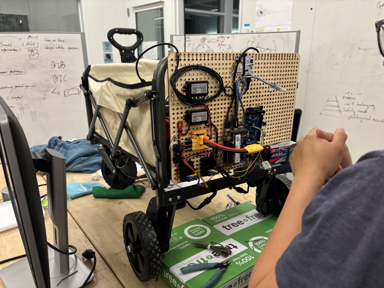
Motor Control & Hardware Integration
cmd_vel messages are split into drive speed (linear.x) and steering angle (angular.z). The drive motor powers the rear axle for forward/reverse motion, while a separate steering motor pivots the front wheels via a steel tie rod. The Raspberry Pi sends commands over UART to the ESP32, which generates PWM signals for the Cytron MDD3A dual H-bridge motor driver. Final integration included mounting all components (camera, Pi, UWB module, ESC, battery) onto the cart chassis with proper cable management.
System Integration & Field Testing
The most challenging phase — bringing all subsystems together. Sensor synchronization between vision (30fps) and UWB (variable rate via BLE) required careful timestamp management. Field testing revealed depth noise in outdoor environments with direct sunlight, BLE connection instability with the UWB module, and battery runtime limitations. Iterative tuning of PID gains, detection confidence thresholds, and obstacle avoidance parameters across multiple outdoor test sessions.
Gallery
Technical Details
Challenges
Depth Noise in Outdoor Environments
Stereo depth accuracy degraded significantly under direct sunlight and with reflective surfaces, requiring adaptive threshold tuning and confidence filtering.
UWB Connection Stability
BLE connection between the UWB module and iPhone was intermittent, causing gaps in backup localization data. Required reconnection logic and graceful fallback handling.
Battery Runtime Limitations
24V LiPo provided only ~25 minutes of operation with all systems active. Power budgeting and duty cycling of non-critical sensors were explored but not fully implemented.
Sensor Synchronization
Vision (30fps) and UWB (variable BLE rate) operate on different timing cycles. Timestamp alignment and data freshness validation were critical for reliable fusion.
Key Learnings
Single-sensor dependency is dangerous — multi-sensor fusion architecture is essential for robustness in real-world conditions
Simulation ≠ reality — real-world noise, lighting variation, and mechanical play introduce problems that never appear in simulation
Hardware integration is harder than software — mounting, cabling, vibration, and thermal management are underestimated engineering challenges
Full-stack robotics (perception → planning → control → hardware) requires deep integration testing that can't be unit-tested in isolation